
Single Stub Matching
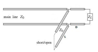
Single Stub Matching using parallel connection.
Stub matches are widely
used to match any complex load to a
transmission
line. They consist of shorted or opened segments of the line, connected
in parallel or in series with the line at a appropriate distances from
the load. In coaxial cable or two-wire line applications, the stubs are
obtained by cutting appropriate lengths of the main line. Shorted stubs
are usually preferred because opened stubs may radiate from their opened
ends.
The single stub match is perhaps the most widely used matching circuit
and can
match any load.
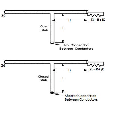
Open and closed stubs with coaxial transmission lines.
The most common method for calculating the lengths in a single stub match is to use a Smith Chart, but for people that not master the Smith Chart, nor the rather complicated calculations needed, I have developed the calculator below. The calculator will calculate one possible solution for a Single Stub Match that you can implement in your antenna system.
To use the calculator you first need to measure the impedance (resistance
+ reactance(j)) of your antenna, this can be done with an antenna
analyzer (i.e. MiniVNA or MFJ-269 or similar). Please be aware of that
many antenna analyzers (like MFJ-269) does not measure if the reactance
is positive (inductive) or negative (capacitive). Antenna analyzers like
the MFJ-269 measures reactance, but can not determine if the reactance is
actually inductive or capacitive. You can usually determine the type of
reactance by adjusting frequency. If the frequency is increased and
the reactance decreases, the load is capacitive at the measurement frequency.
If the frequency is reduced and the reactance decreases, the load is inductive
at the measurement frequency.
Important: To measure the antenna impedance correctly,
you need to measure the impedance through a transmission line not more
than a small fraction of a wavelength long. This may make it difficult
to measure the impedance of VHF and UHF antennas correctly.
When you have measured the impedance of your antenna, enter the frequency in Megahertz, the impedance of your transmission line, the resistive part of your antenna impedance, the reactive part of your antenna impedance with the correct sign, and finally, the velocity factor of your transmission line. Then click on the "Calculate" button.
The calculator will calculate the length of the stub (L), and the distance (D) from the load (usually an antenna) where the stub shall be placed.
When you build the match, use the same coaxial cable for the stub as used for the rest of the antenna system (or at least the same coaxial cable as used close to the antenna), then use a T-connector to attach the stub to the rest of the coaxial cable. When measuring the length of coax D and coax L, remember to include the lengths of the connectors and the T-connector.
This page was last updated 13.05.17